There is plenty to be learned here, and if youâre the DIY type, youâll enjoy tackling this project as much as I did. However, there are a few things Iâd do differently if I had to do it all over again, I made some mistakes, and learned a bunch. So take notes and know that youâll be better equipped to troubleshoot if something does go wrong after youâve done the legwork and installation. Plus, youâll save a ton of money being self-sufficient. Use this gallery as a blueprint to make upgrades to your rig.
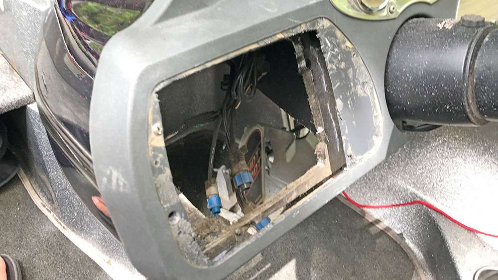
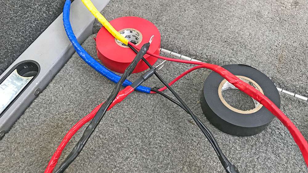
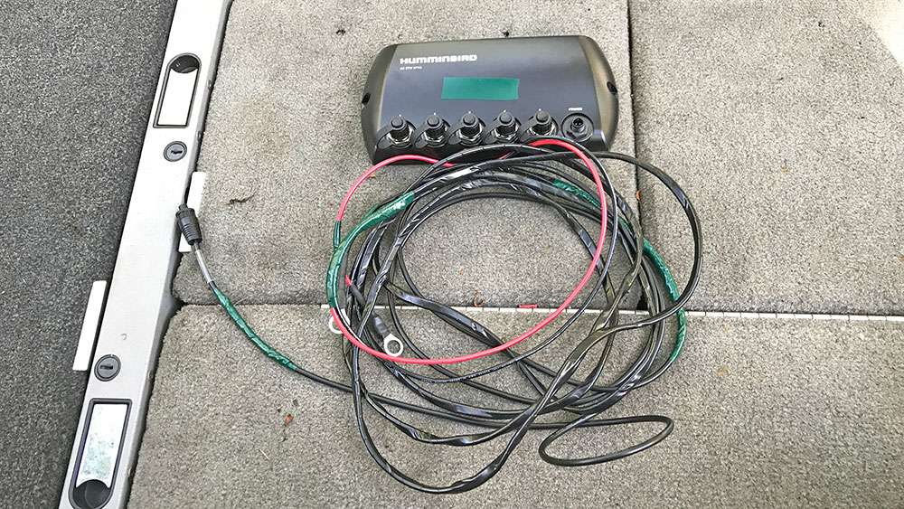
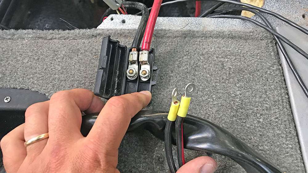
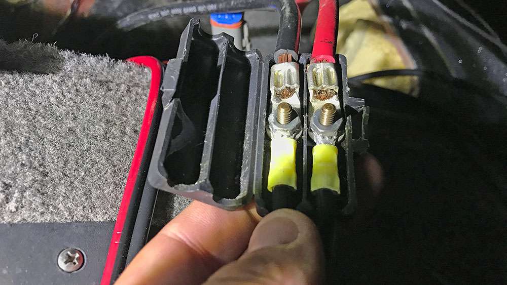
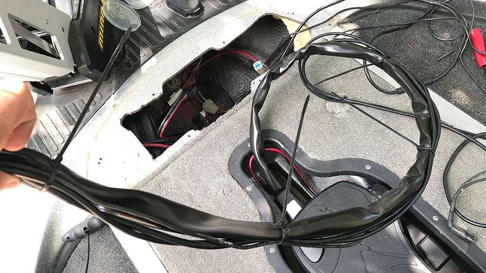
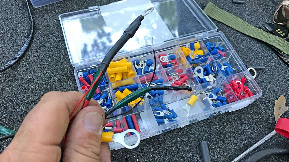
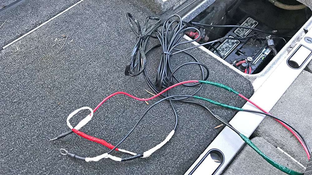
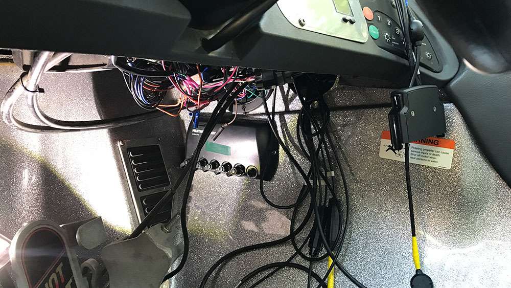
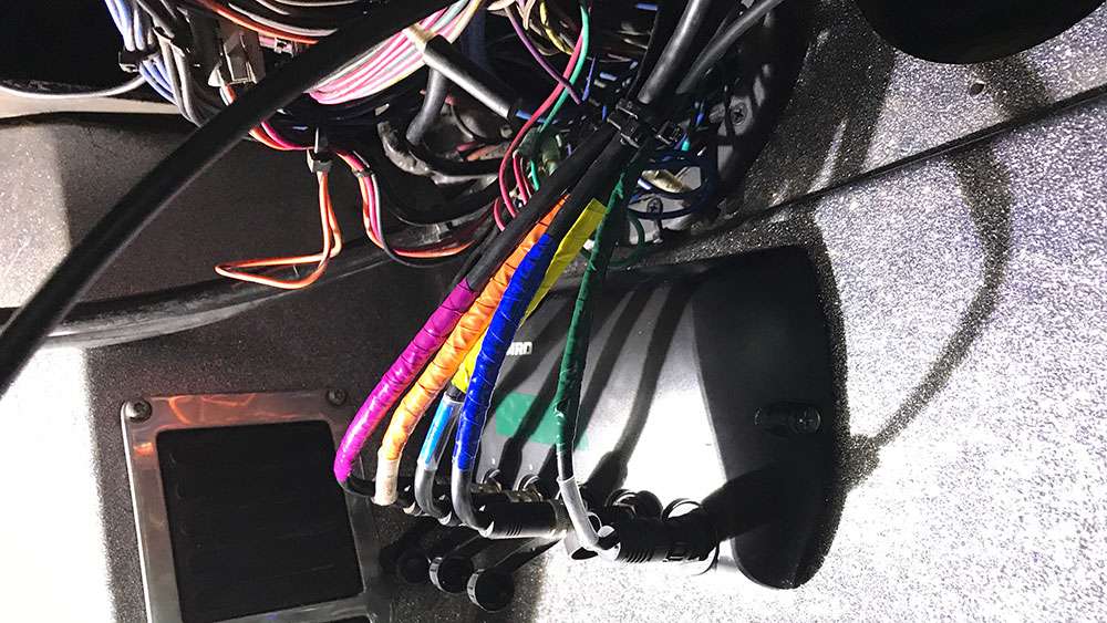
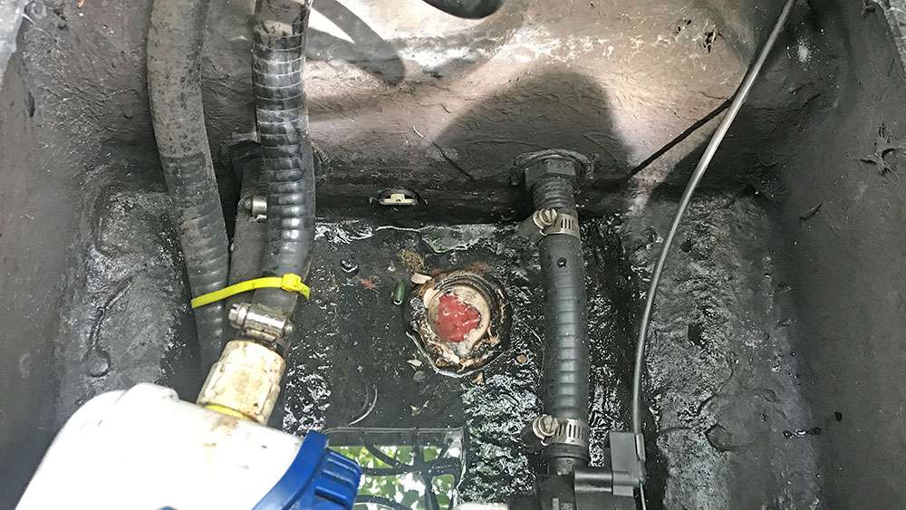
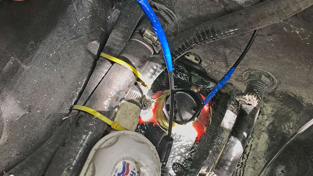
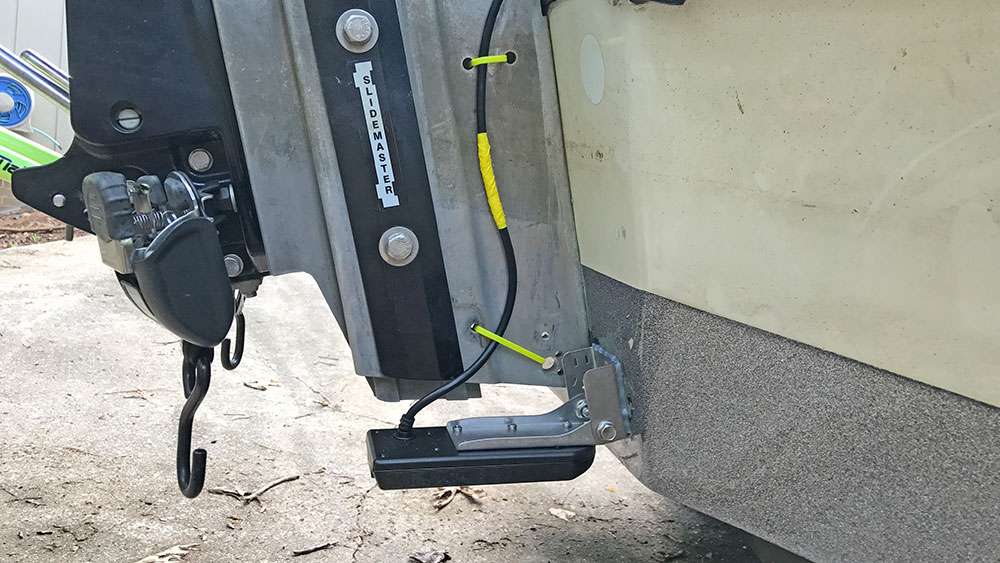
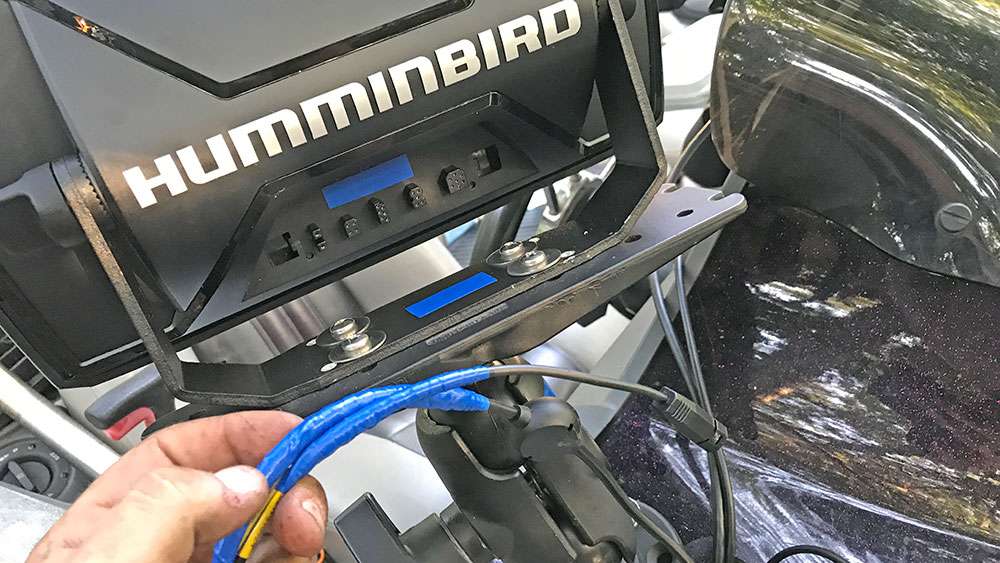
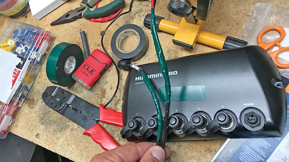
I could have run the wires to the electrical board behind my dash, but Iâve actually found that those connections arenât as secure and have a tendency to break. I prefer to run the lines straight to the cranking batter. Again, this is my method of connection, and I did place an inline fuse on each line as an added precaution, but neglected to take a photo. See the blue and yellow electrical tape? More on that to come.
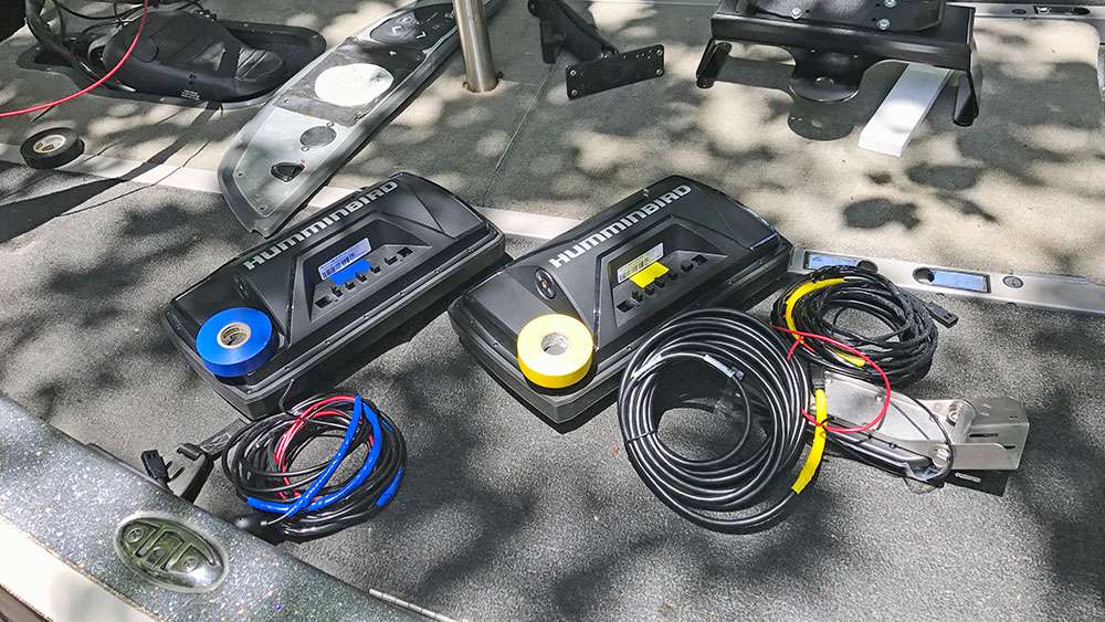
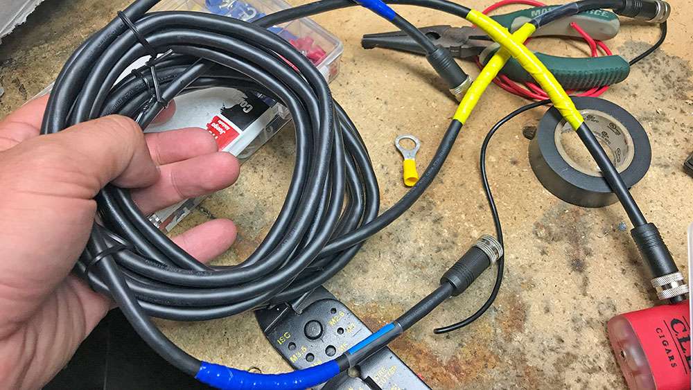
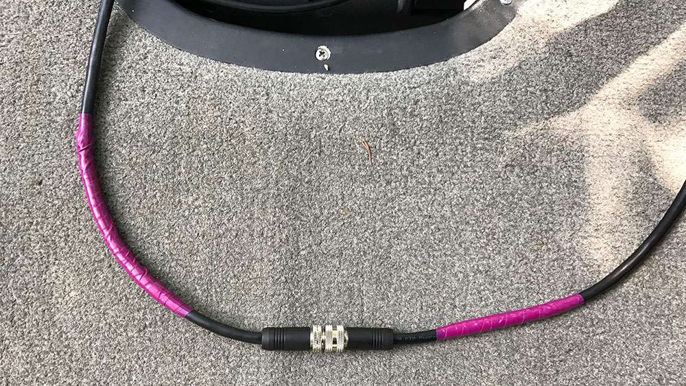
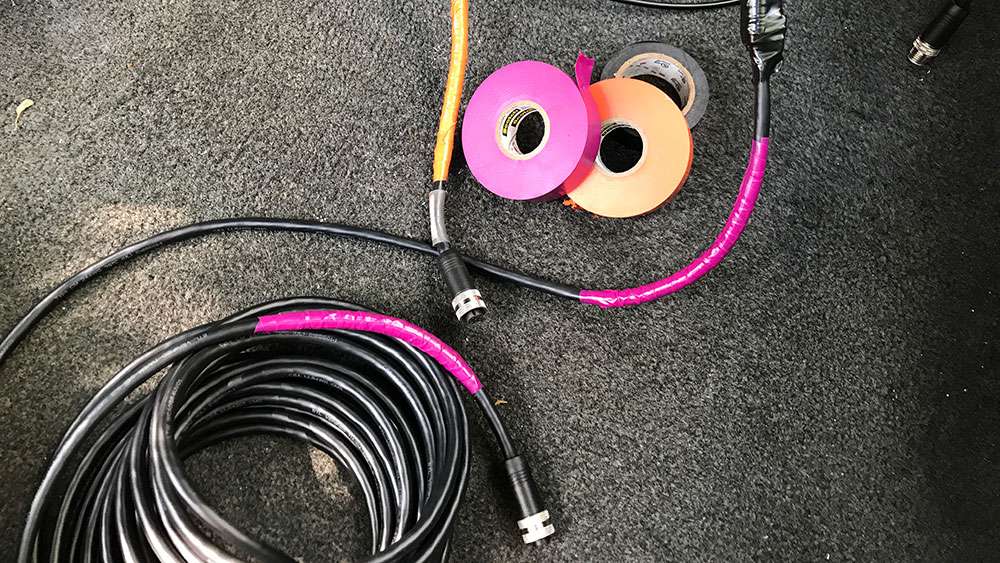
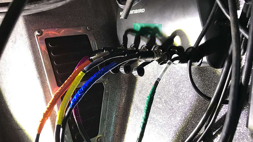
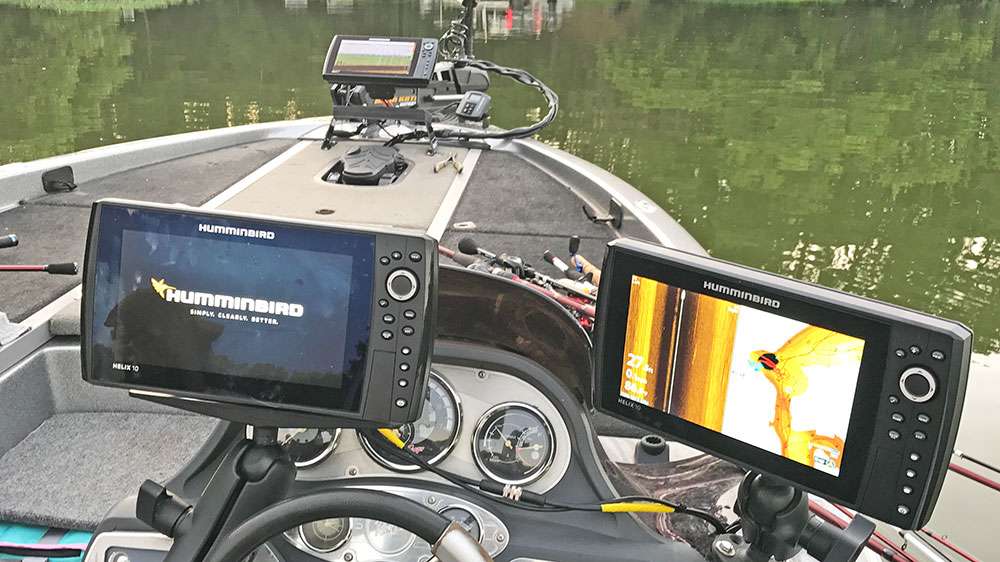
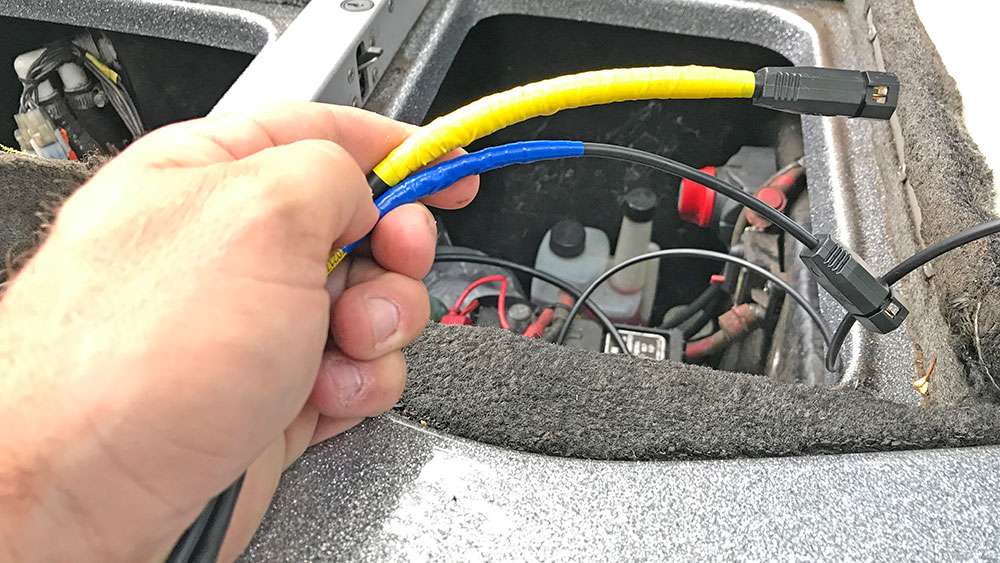
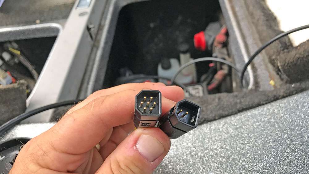
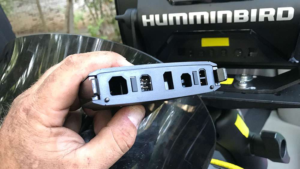
I tape both ends of every cable to relate to which unit it will be connected to.
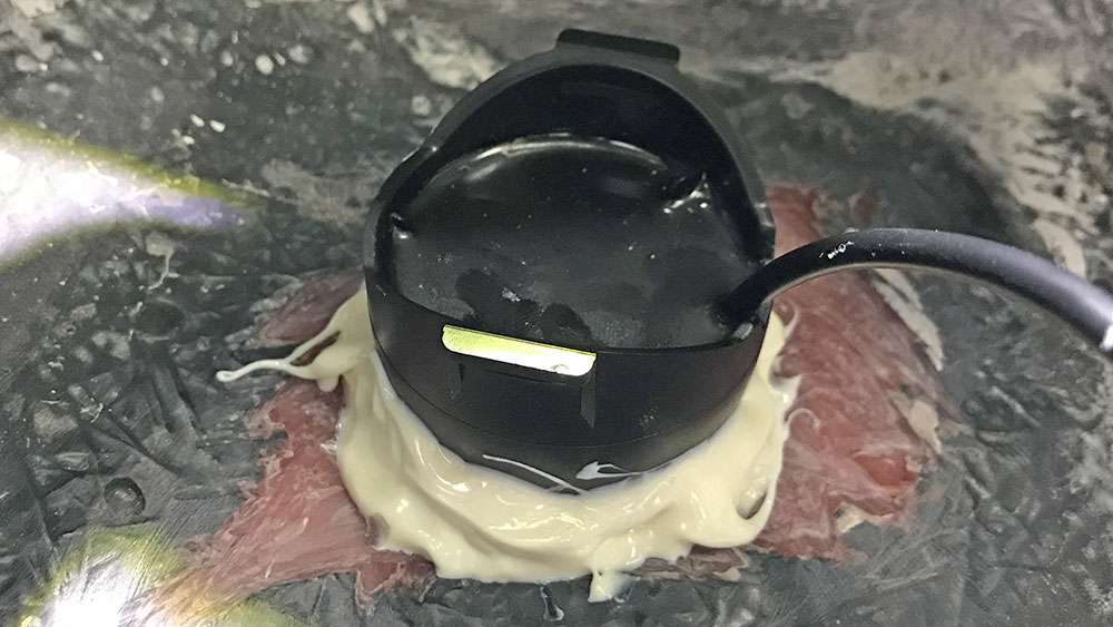
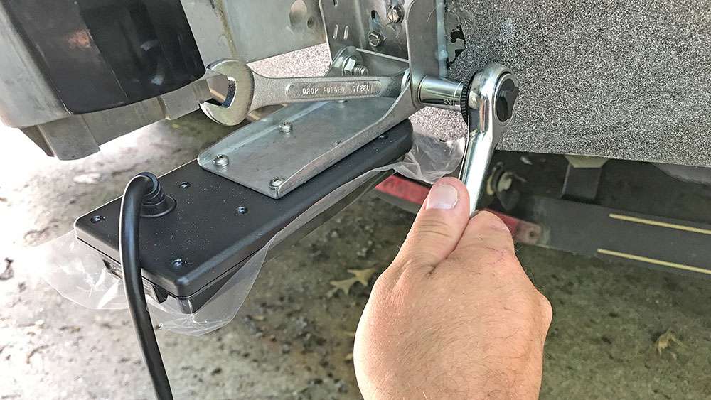
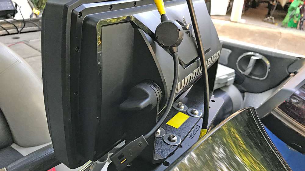

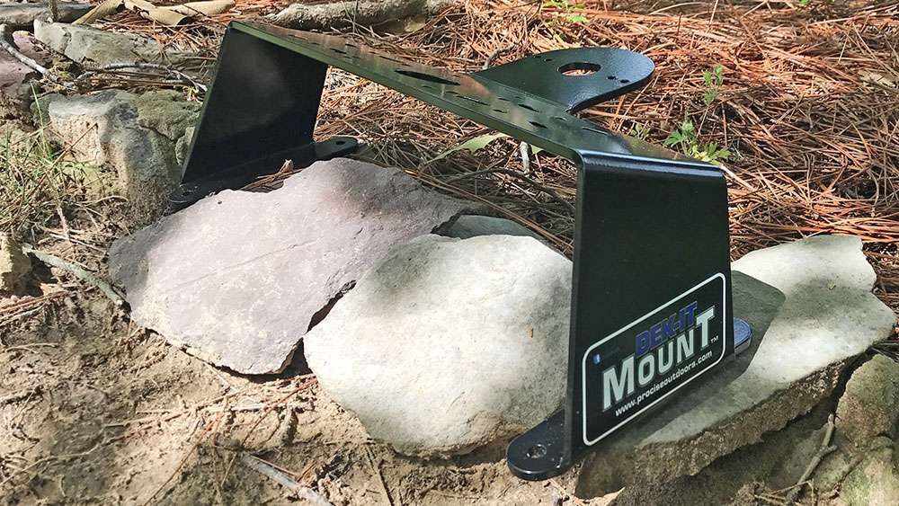
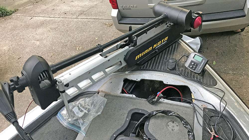
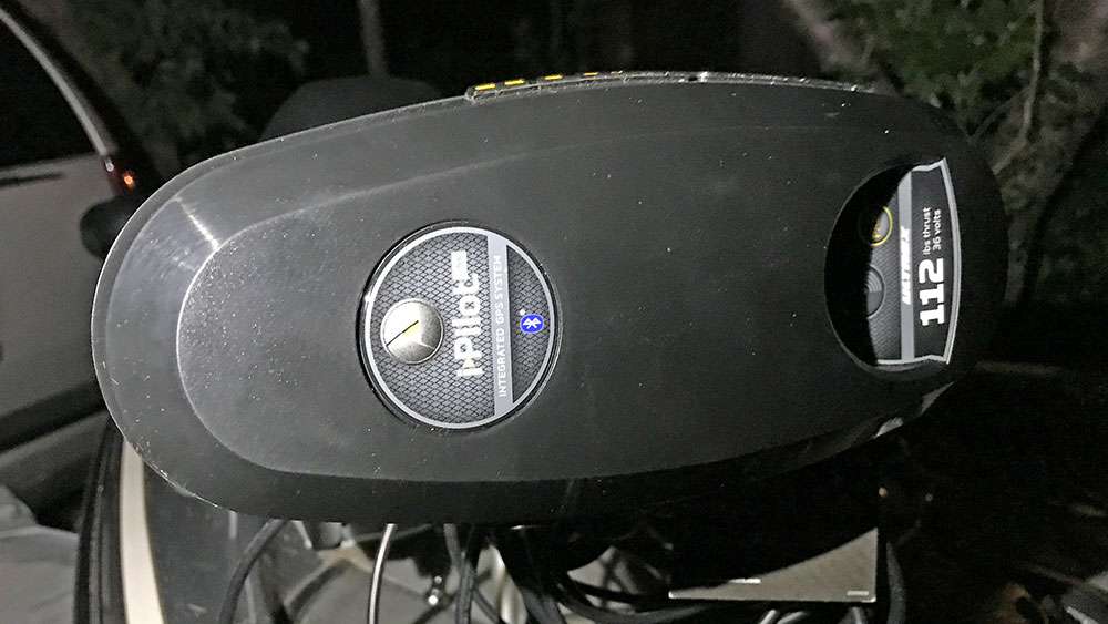
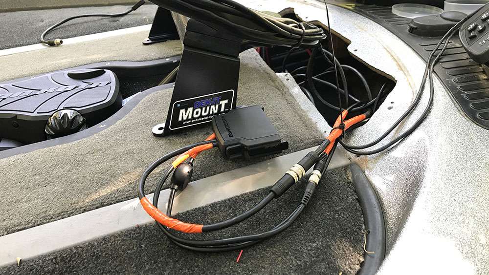
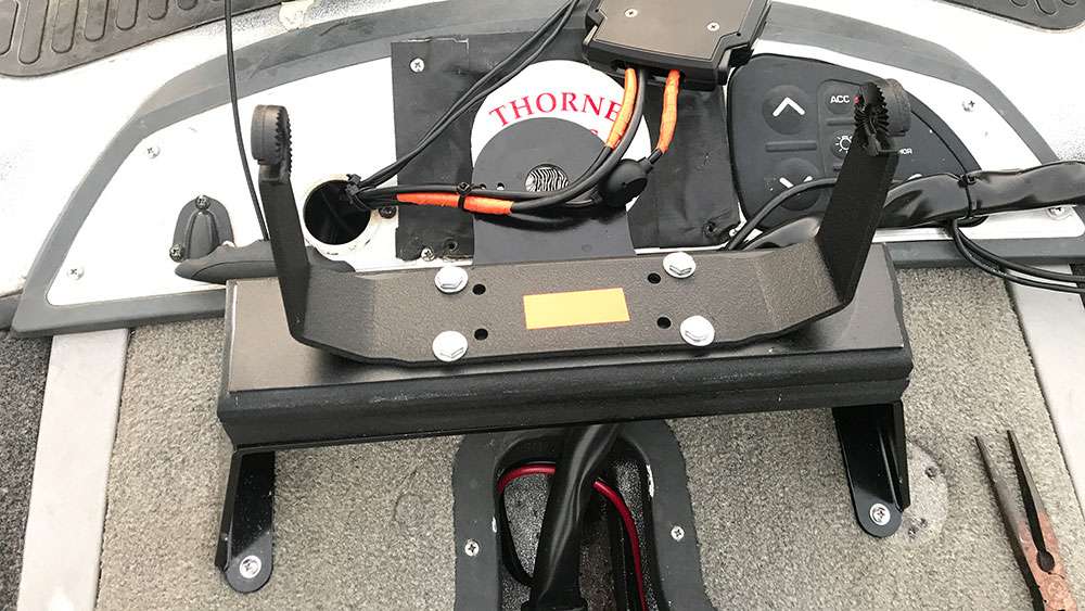
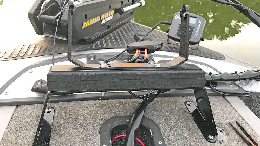
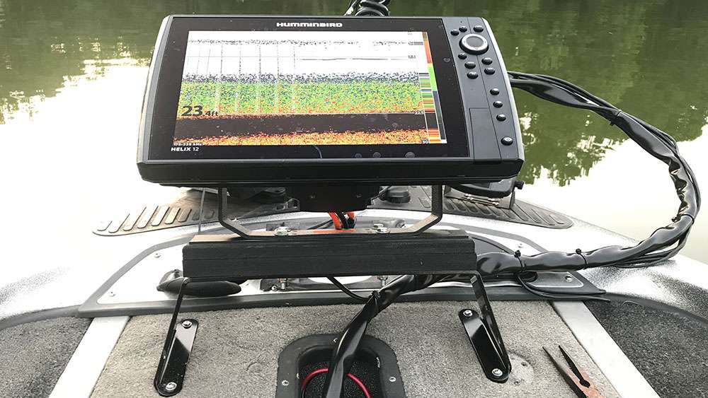
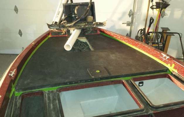
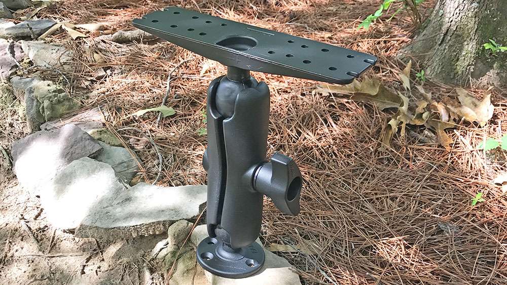
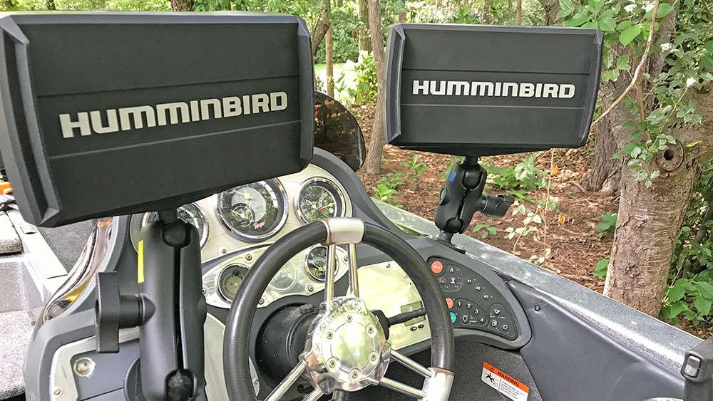
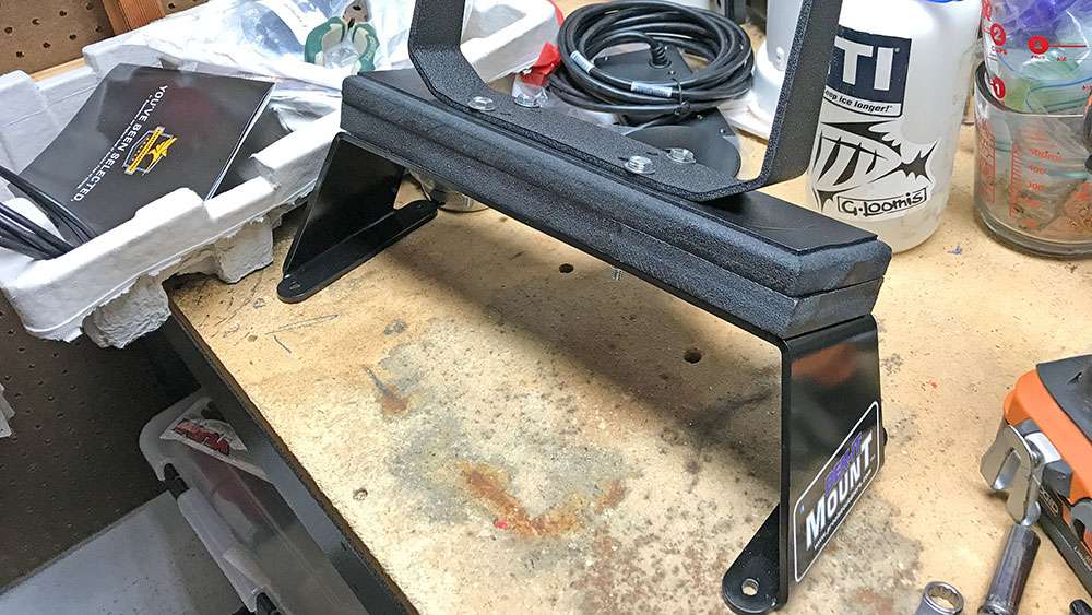
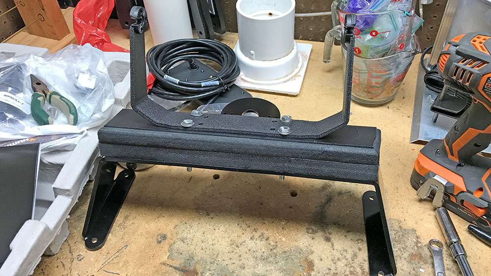
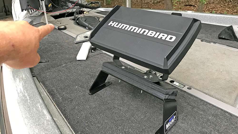
that would sit forward of and above the trolling motor pedal. I decided to go with the Dek-It 22.5 GPS. The mount is angled backwards to provide a user-friendly angle. On the front side of the mount you can also mount a GPS puck. The Helix units have the GPS transponder installed internally.
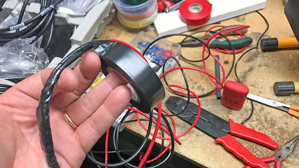
Yes, Iâm somewhat OCD, but trust me on this organization thing, if you ever have to pull cables or fix something, youâll be very glad you did it this way.